Year in Review With Rising Tide Research Foundation
Scroll DownAnchors Up!
Starting in the summer of 2025, I had the opportunity to work with a start-up research society whose mission is to develop open source technology for electric marine vehicles and to educate the public about clean-marine technology more widely. This was somewhat outside my wheelhouse as I’m not exactly a sea dog, but even I see the necessity to convert a lot of diesel motors to electric in the coming years. Also, I admire the research approach (as opposed to immediately productizing and prematurely founding “The Tesla of boats”). However, the seafaring action was going to be on the opposite side of the country from me, and I’d be here on the East Coast in my element: developing hardware and firmware. So from summer ‘25 to summer ‘26 I spent about 20 hours a week on a handful of projects.
Boat in a Box
Something that seemed immediately important was that I have access to a scale model of the electrical system of our flagship vessel design, complete with the same Battery Management System (BMS), Solar Charger, etc. This would be used to test my board designs “in situ” during development despite not having access to the boat. I mocked up a frame out of aluminum extrusion in Fusion 360 to accommodate everything and protect the 16 LFP (lithium iron phosphate) cells of the 48V battery.
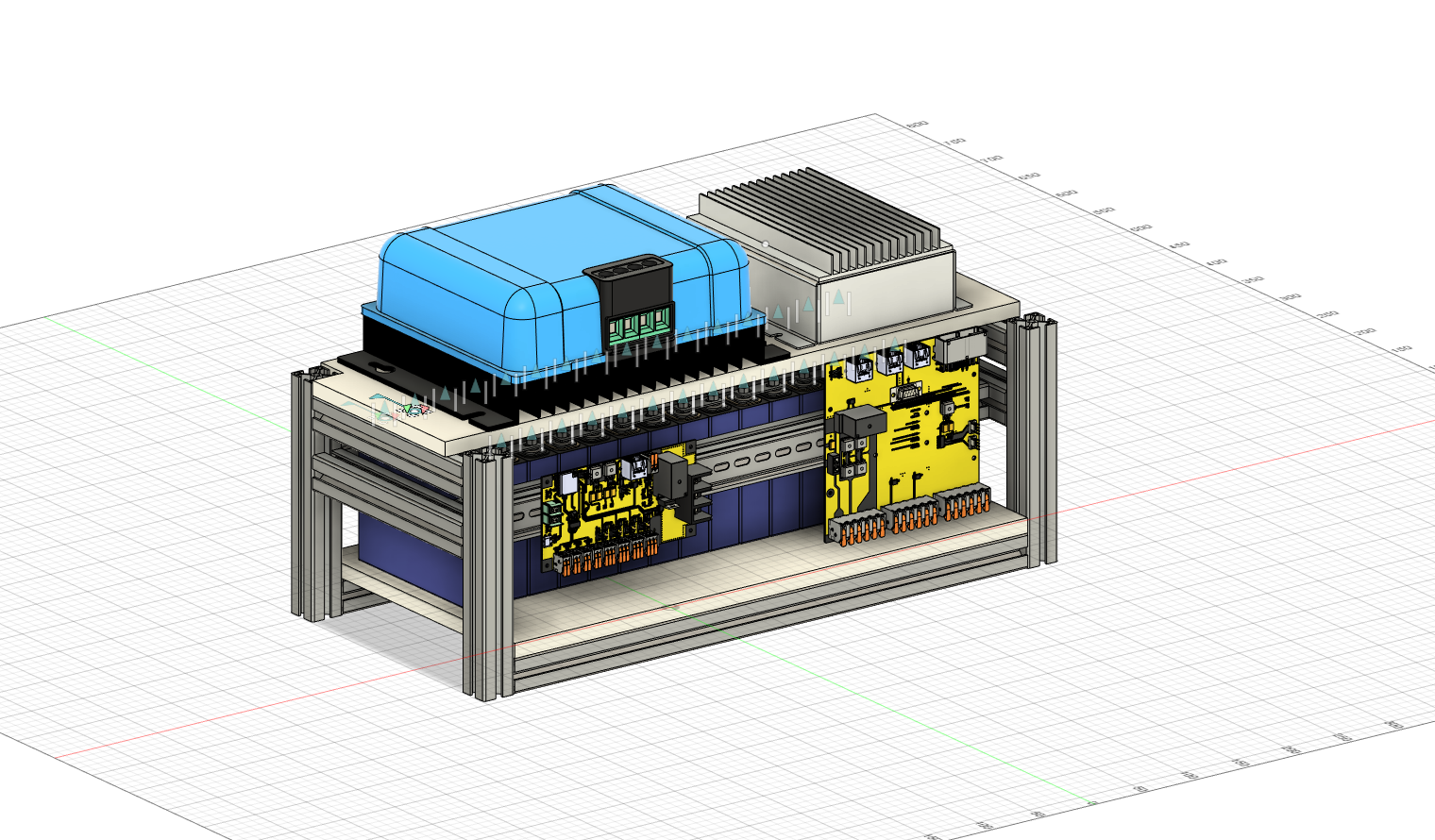
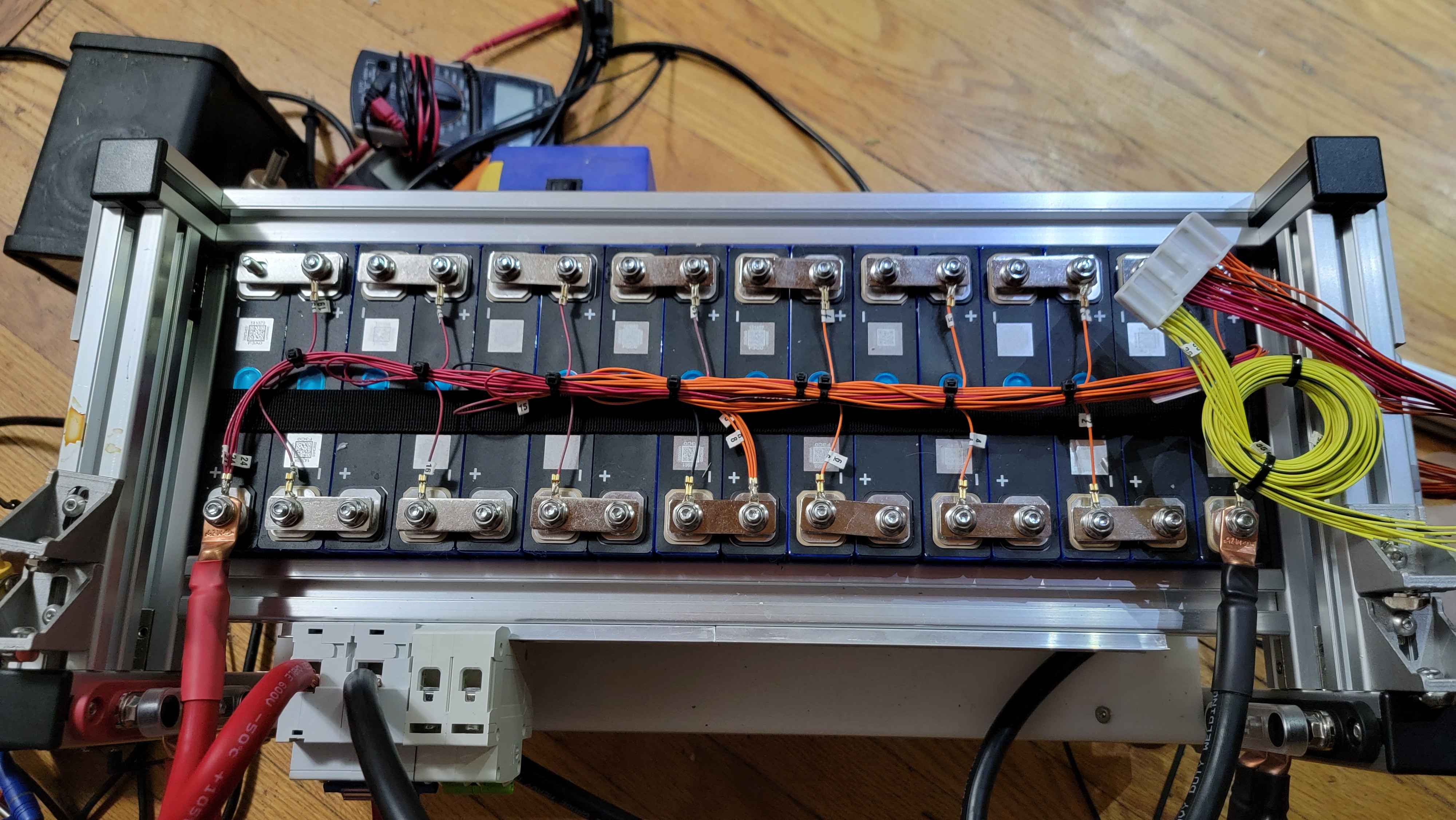
Anyone familiar with electric vehicles may be surprised to learn that this 48V battery actually represents the boat’s main system voltage and not an auxiliary battery. While this does create some challenges (indeed the propulsion system draws a theoretical 600A at full chooch) there are advantages for the solar charging, safety shut-off, and other subsystems. The actual batteries going into the boat are made from bundles of BYD Blade Cells. These bundles provide mechanical compression to the cells, preventing charge cycle damage, but they also provide manageable units that can be slotted into a larger rack. My bench top model is made up of 50Ah cells that wouldn’t be seeing a lot of action, so I didn’t clamp the cells beyond strapping them down with some nylon webbing.
I made some reasonably stiff, non-conductive shelves out of HDPP sawn from commercial cutting boards (shoutout Quiet Nerd) and bolted down the solar charger and BMS. A piece of extrusion running across the front of the unit got some DIN rail to mount circuit breakers and PCBs. Part of the impetus behind building everything into a little aluminum frame was to make it easy to move around, not just in my own lab but also whenever I needed to hand it over upon the end of my contract. For the sake of luggage, I threw a couple handles on it and some rubber feet.
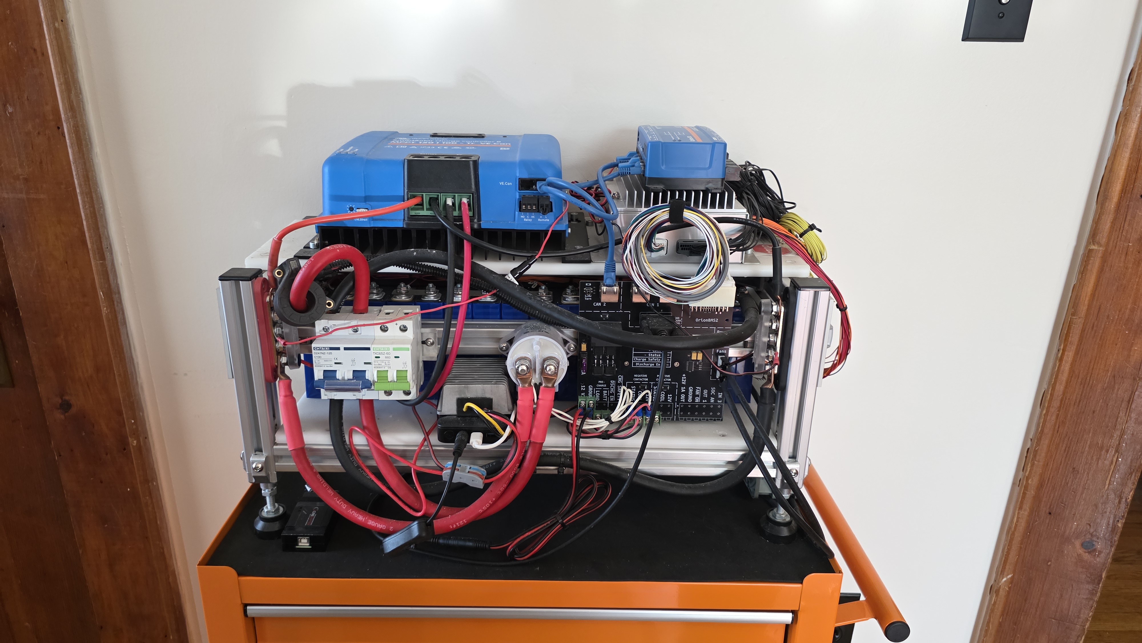
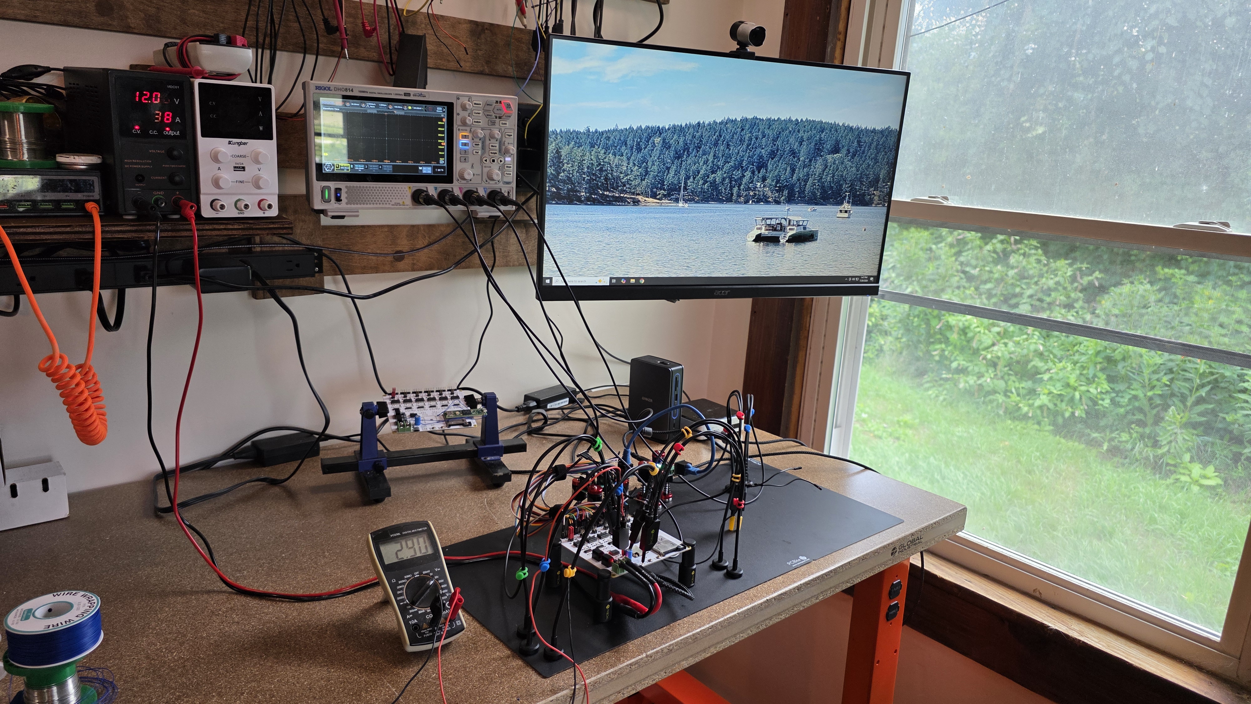
Ultimately, I spent most of my time optimizing SPI transfer speed on the ESP32 for a different project so the test bench—admittedly—got pretty light use. It did end up being helpful while playing with the BMS configuration software in order to test a breakout board for the main I/O connector. It was also planned to be a test source to stress-test load control relays. Speaking of which…
CAN-Networked Load Controller
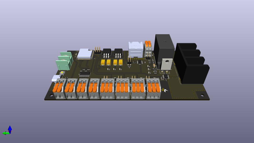
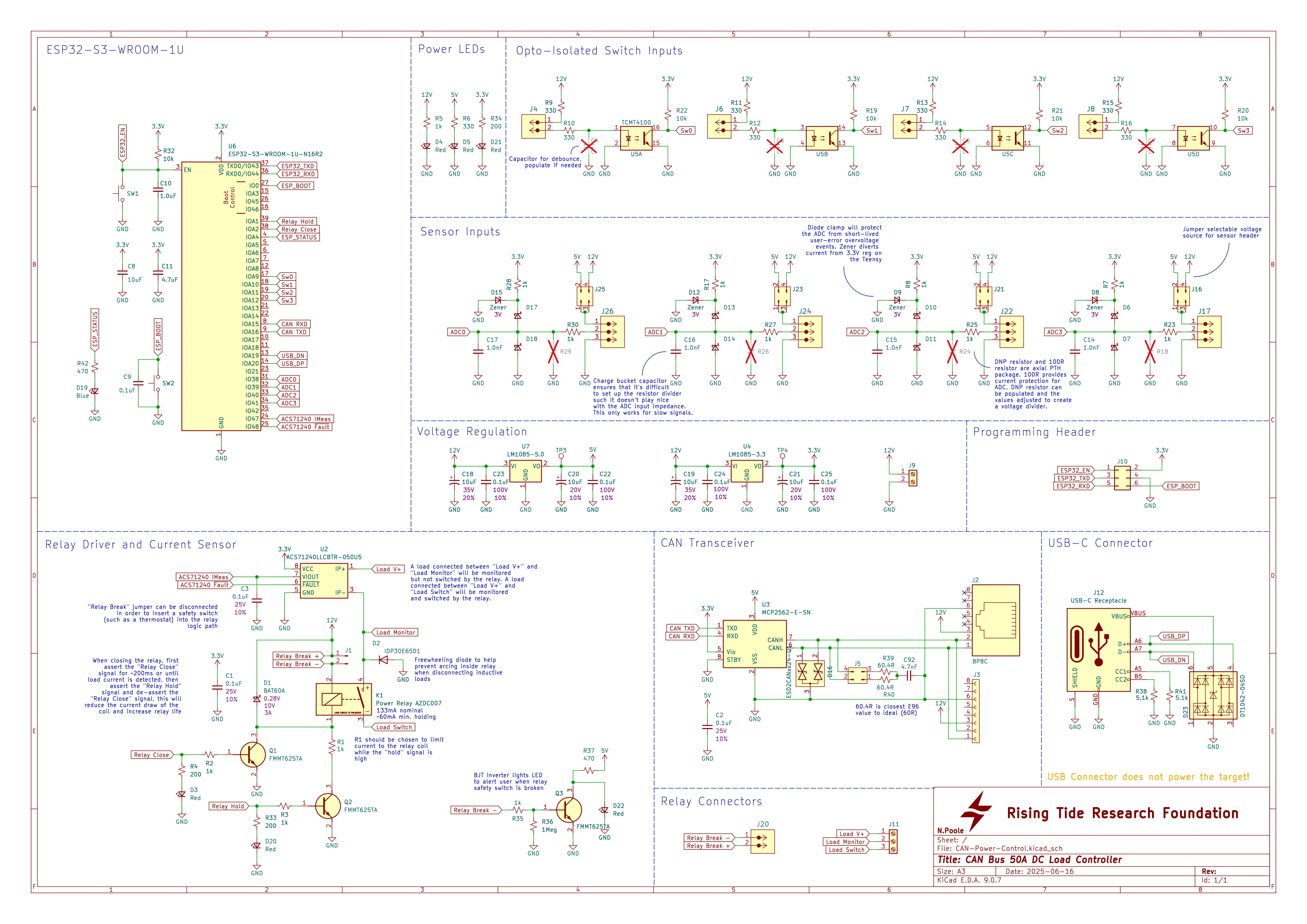
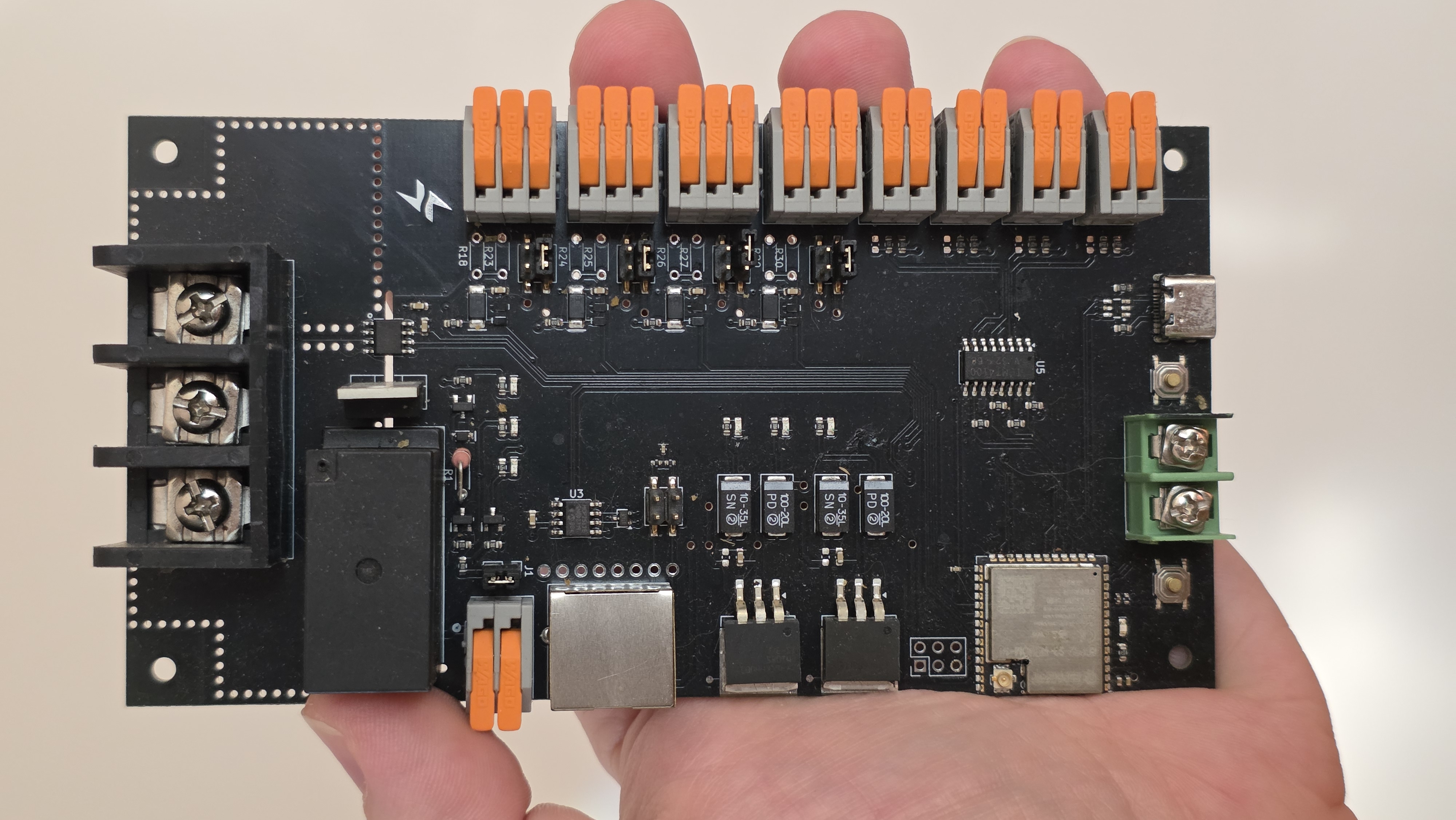
Because CAN is the control backbone of the boat, a number of CAN-controlled peripherals need to be designed to attach to various appliances and sensors. One appliance that might not immediately spring to mind is the water heater, but because it’s a large resistive load it’s a great place to dump “extra” power when the batteries are full and there’s still ample solar capacity. I designed a load controller for the water heater capable of switching and monitoring a 50A load with level-shifted GPIO for reporting temperature and water level data along with the current draw.
Switching and Monitoring 50A DC
50A at 48VDC is kind of a weird ask. It’s a lot for a small board-mount relay, but it’s not what you would think of as contactor territory. It took some time to dig up the American Zettler AZDC007 50A Miniature Power Relay, a miniature general purpose relay rated for 50A at 65VDC. To switch the relay coil, I chose a fairly standard SOT23 NPN BJT with plenty of current overhead. I actually used two transistors so that the controller could reduce current to the relay coil after activation. Because the relay was likely to spend a lot of time closed, it made sense to reduce coil wear by not hammering it with the full activation current all the time. This relay hold-current circuit could have been passively controlled with an RC timer, but we have a lot of GPIO on the ESP32-S3-WROOM so it made sense to hook it up. Theoretically, because the controller is also aware of the current flow through the relay, this could give the firmware more tools for clearing potential faults.
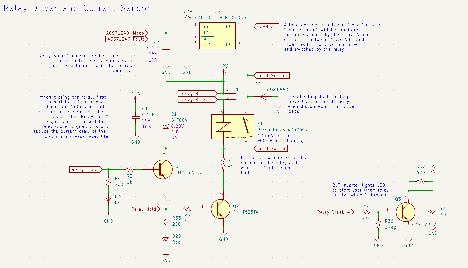
A jumpable switch-closure was also provided in line with the coil in order to allow for a safety switch to completely disable the relay. Note, this would not disconnect the load in the event of a catastrophic relay failure, like a welded contact, but it also doesn’t require the safety switch to see the entire load. In the case of our water heater, this switch might be a thermostat or a pressure switch. It would be handy, for maintenance purposes to be able to tell at a glance if this relay break was opened, so a BJT inverter connected to the coil side of the switch lights an LED whenever the coil can see ground but not 12V. Because the coil is switched by the controller from the low side, the only situation where this should happen is when the relay break is open (or, I suppose, if the coil was destroyed). Finally, while the water heater was the initial inspiration for this design, I was told to generalize it as much as possible for other applications, so a beefy freewheeling diode was added despite probably being unnecessary for this application (heating elements being purely resistive loads).
Current monitoring is handled by an Allegro ACS71240, a very cool current sensor IC that works by funnelling the sensed current through a copper conductor in the chip, very close to the die layer, where a Hall effect circuit senses the magnetic field generated in the conductor and correlates it to the current flow. This is like a current clamp meter but in a surface mount package. And despite its small footprint, the ACS71240LLCBTR-050B5 can sense ±50A DC. Suitably large copper pours and screw terminals provided a secure connection to the load. A separate terminal was provided for applications that wished to bypass the relay entirely and just use the board for current monitoring.
Obsessively protected GPIO
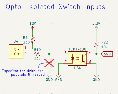
The ESP32S3 has a lot of GPIO, so it would seem a waste not to break them out as sensor inputs for whatever application might use them. Unfortunately, I have no idea what things might get connected to those GPIO and the ESP32 is a 3.3V system that is not particularly tolerant to abuse. Providing safe switch-closure type inputs was easy enough, I just put opto-isolators in front of some GPIO pins with an optional capacitor footprint for debouncing.
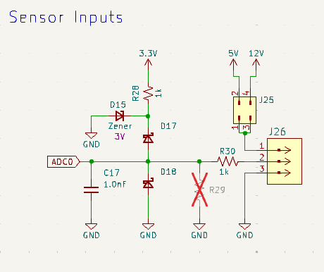
The analog inputs are a little bit trickier, but they end up being basically a collection of slow signal conditioning’s greatest hits. These inputs are basically intended for industrial sensors, sensor control boards, amplified sensor outputs: applications where you give some device a voltage and it returns a signal scaled to that voltage. The first priority is obviously to keep the ADC in the ESP32 safe, even if we have to clip the signal. That said, the ability to scale the signal in some way is obviously important as well. The first line of defense is just an in-line resistor to limit current to the ADC. A second resistor footprint is provided that utilizes the current-limiting resistor as half of a resistor divider to scale down a large signal. The second defense is a Schottky diode clamp to keep the signal between 0 and 3V (or close to it, Schottky diodes were chosen for their low forward voltage drop). A Zener diode on the top end of the clamp will try its best to keep the 3.3V rail from getting dragged up during an overvoltage event. No one should rely on this diode network to clamp signals that are regularly out of spec, but it should prevent damage from brief user-error events. Finally, an external charge-bucket capacitor provides a current reservoir for the ADC sample-and-hold circuit in the event that the resistor divider is configured with super high impedance.
For convenience, these pins are flanked with ground and Vout pins to power the sensors. The Vout is selectable between 5V and 12V because we have regulated sources for those on board already, and they’re relatively common supply voltages. Auto-scaling for the ADC input would have been really cool, or at least scaling to the selected Vout, but it adds a lot of unnecessary complexity to a design that’s probably going to be configured once on installation and never touched again.
Communication
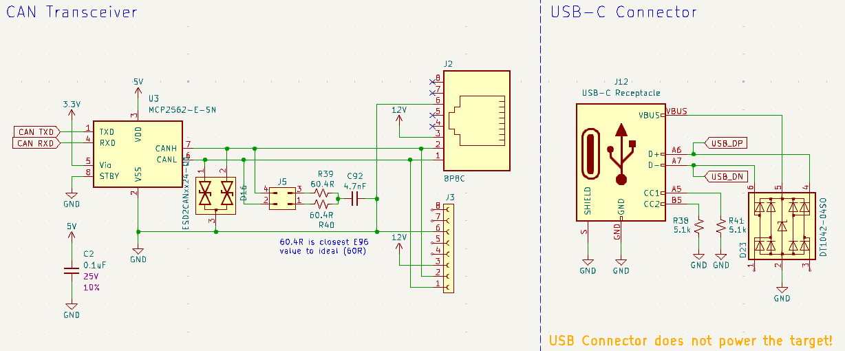
Digital comms on this design comprise only the USB connection for programming and an 8P8C connector for CAN. The ESP32 has native USB support, so we only need to support a connector, really. Because I chose a USB-C connector, we also need a pair of 5.1k pull-downs on the CC pins. Finally, we might as well throw a TVS diode network on there for protection.
The CAN bus is handled by the CAN controller on the ESP32 in concert with the super common Microchip MCP2562 CAN transceiver. The CAN lines are protected from ESD by a dual-channel TVS diode made for CAN applications. The jumpable termination resistor is a split termination, providing improved common mode noise resistance and high-frequency AC rejection. It’s an easy change from a single 120Ω resistor and it reduces potential radiated EMI. Unfortunately, while 120Ω is not a super common value, it is at least E192 whereas 60Ω is an extremely specialized resistor. I chose to substitute for 60.4Ω which is an E96 value and, unless you’re shelling out for high-precision resistors, is well within tolerance. Chances are your transmission line is not so perfect that it matters, they could probably be 56Ω or 62Ω if that’s what’s handy.
Firmware
I never got to write firmware for this thing because the CAN Gateway was always higher priority and became something of a bear. In fact, the load switching portion has not been practically tested, there’s a water heater element sitting on my bench right now which was going to be my test load but, again, priorities. Just something to keep in mind if you find yourself wanting to use this design. The firmware shouldn’t be complicated, though, and it’s going to be fairly application specific. In the case of a water heater, it would periodically report status, water temperature, and current usage, and keep an eye out for on and off commands. It may even just look for particular remote frames and reply to them with sensor data. Obviously, it would alert on certain fault states and actuate the relay hold-current circuit correctly. Probably it would report the raw ADC values, switch-closure inputs, etc. on a serial debug menu over the USB connection. Again, it really depends on the particular application.
KiCAD Library
After working on my first design for RTRF, and collaborating with other engineers, it seemed like a common parts library would be helpful. Drawing from a common library prevents duplicate work and simplifies the DFM process. While RTRF isn’t in the business of selling hardware, we still need to build these designs for testing, and it’s helpful not to be ordering 5 SKUs of identical resistors. It’s also a form of vetted knowledge that outlives any one engineer’s time with the org: These are parts that we’ve used before, here’s a symbol, here are the datasheets, here’s an LCSC SKU.
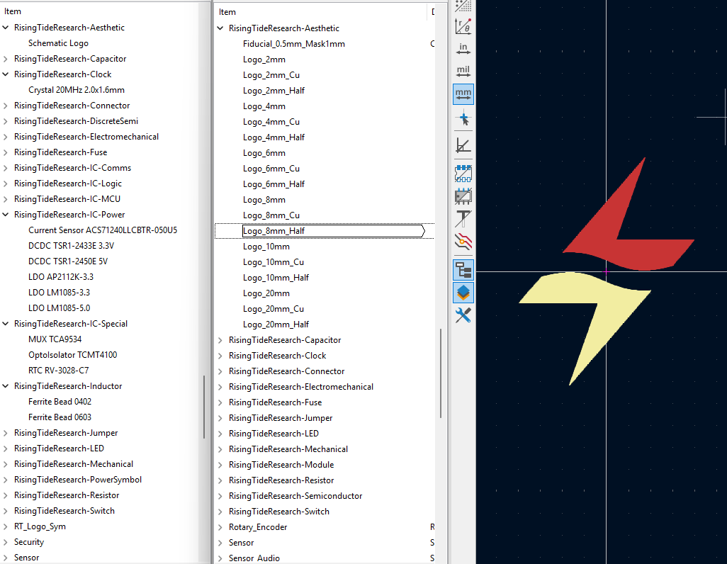
I modeled the library (actually a collection of libraries) after the SparkFun KiCAD library out of force of habit. The symbols are categorized by function and follow the unified formatting rules: closed shapes are filled, pins are medium length and arranged prioritizing schematic legibility, Value and Reference are both visible. The footprints are similarly categorized, although certain categories are combined (for example: semiconductor). Every symbol in the library is associated with a SKU for fast BOM generation for JLCPCB assembly and every device that’s not a passive or a common connector has an associated datasheet which is embedded in the symbol file and not a link to an external resource that may disappear.
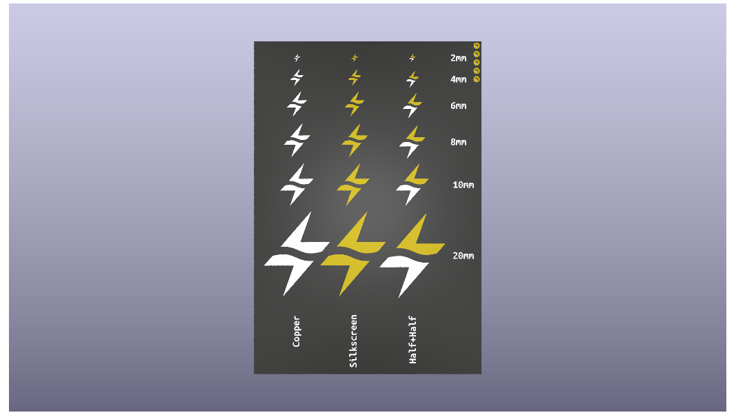
As soon as the foundation had a logo, I added various sizes and treatments of the logo to the footprint library as well. These looked really nice on the prototypes, but I think I was the only engineer with a passion for branding.
framedash and veye
As it became clear that CAN traffic analysis and reverse-engineering was going to be a large part of the job going forward, I recognized the need for some software tools. There may well be existing traffic analysis tools for CAN that I’m unaware of (Maybe a MATLAB or Wireshark plugin?) but what I could find was either too much or lacked some specific functionality that I needed. As a result, I spent a few weeks writing a pair of python tools called framedash and veye to help me make sense of CAN traffic on undocumented buses.
framedash
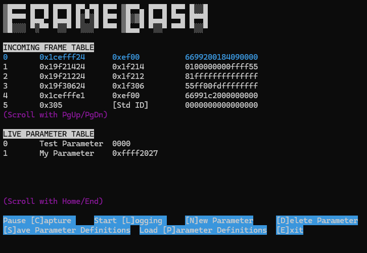
From the framedash GitHub repository:
framedash provides a Terminal User Interface (TUI) for monitoring and logging CAN traffic while extracting specific data based on pattern matching. framedash is intended to aid in the exploration of proprietary higher-layer protocols on the CAN bus.
When I started trying to reverse the frame composition of some of the CAN/NMEA2000 traffic that we had collected from things like the throttle units and motor controllers, I found that I was doing a lot of staring into the Matrix code looking for patterns.

It’s a correlation task: You know roughly what was happening during the log recording, and you look for bytes changing in the stream of CAN frames that describe that behavior. This wasn’t entirely fruitless, but not everything is encoded in single bytes and not every ID is of interest. framedash is designed to make this “Matrix gazing” easier and to help tease out changes in particular values within target frame IDs.
As an example: Say you know that the position of a knob is communicated over the CAN bus. The first thing you might do is to connect a data logger and record the CAN traffic while you turn the knob from stop to stop over the whole range. Then you might open the log for playback in framedash and watch it back. The incoming frame table will list each unique frame ID and update their values as new frames come in with the same ID. This makes it easy to tell at a glance when a byte or sequence of bytes changes. This might be the end of the hunt if your value of interest is a single byte or is arranged big-endian and is therefor easy to identify.
Now let’s say that instead of a knob, you’re looking for the value of a thermometer. You’ve observed a byte that you think could be your value of interest, but you’re not certain. If you know approximately what value you’re looking for (say, something that looks like an ambient temperature) then you could make a new parameter for that byte that displays in decimal and check whether it resembles a temperature. If not, maybe incorporate the byte next to it and check, maybe it’s encoded into two bytes for some reason. You can make a bunch of parameters and see which ones track the expected data best over the course of the log.
Finally, let’s say you’ve been working on a particular bus for a while, and you’ve built a parameter list that extracts all of your values of interest and displays them in the parameter table. Now you can look at live traffic on your bus with all of your parameters being extracted live. You can even record a log of your parameters in CSV format for graphing.
There are a lot of ways that framedash might be useful, and I’m sure that there are features that are missing just because I haven’t imagined a need for them yet. That said, it’s been useful to me, and maybe it’ll be useful to you!
veye
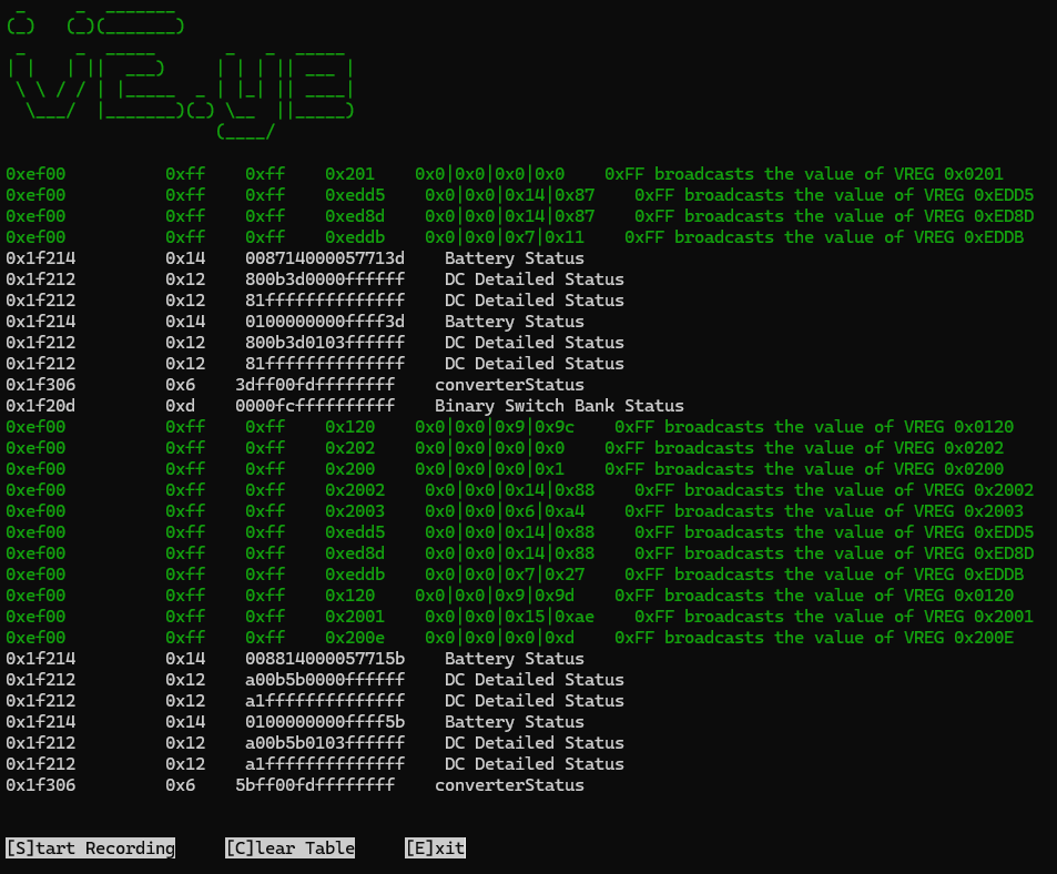
From the veye GitHub repository:
veye is a Python utility for viewing and logging Victron VE.CAN traffic and decoding Victron Register (VREG) messages. Victron products implement a system of “registers” which are read/written using proprietary NMEA2000 messages. These messages can be identified by their PGN in the Addressable Proprietary Message range (0xEFnn/0x1EFnn) and the presence of Victron’s Manufacturer Code (358) in the first two bytes of the data field. Information regarding the message format and certain product registers can be found in the Victron Public White paper found in this repository.
veye detects these Victron messages and breaks out various fields for easier viewing. For Victron Command messages, veye describes the message in natural language. For PGNs which are not proprietary, veye displays the raw data fields and gives the name of the PGN for reference.
veye is a sort of “sister utility” to framedash, a live table for information that wouldn’t fit on the framedash dashboard. veye is specifically for “Matrix gazing” at VE.CAN traffic. Because VE.CAN is a layer on top of NMEA2000, it’s not always obvious what’s happening inside the “data” fields of a VE.CAN frame. veye implements the same live frame table as framedash, but it breaks out and translates the encoded fields. It also recognizes “command register” messages and translates them into plain text to make VE.CAN traffic a little more intelligible. veye is a good first step for identifying IDs of interest in VE.CAN traffic before moving into framedash for further analysis.
6 Channel CAN Gateway
This was the project that I spent the most time on during my contract with RTRF, and it was also the most frustrating and rewarding.
The necessity of the CAN Gateway branches from the fact that, although most of the boat’s systems speak CAN, not all of the systems are able to share a bus. Sometimes this is because of unavoidable ID collisions, sometimes it’s because a device is less tolerant of certain message types. In any case, everything still needs to talk to each other somehow. The CAN Gateway’s job is to sit on all of these buses and move messages between them while assigning compatible IDs, so as to allow these devices on different buses to communicate. As long as it’s on every CAN bus, it also makes sense for the gateway to act as a data logger, recording all of the traffic to an SD card. Finally, we identified that there may be a need for transformations to be applied to incoming frames before they’re retransmitted. We may even want to generate our own frames. For instance, we may want to report data from a sensor to a gauge or dashboard that it wasn’t designed for.
So the initial concept for the CAN Gateway requires these three functions:
- Capture and record CAN traffic on 6 channels at 250kbps
- Recognize target frames by ID and retransmit them on one or several buses
- Perform transformations on target frames and transmit new frames as a result
I chose the ESP32S3 as the controller for this project (which I now consider a mistake for reasons that will become apparent) on the assumption that splitting all of our systems over as many as 6 CAN buses would result in very low utilization and at only 250kbps, the ESP32 would have no trouble keeping up. I had worked with the ESP32 in the past and, although I rarely found any need for it in my projects, I thought the relatively fast dual-core architecture would be more than capable enough. Unfortunately, even reliably logging the incoming traffic on 6 CAN buses at anything close to full utilization was a struggle from day 0.
I wrote the firmware for the CAN Gateway in Arduino, and I know that there are a lot of people wondering why I would do that. Indeed, I have experience working with the ESP-IDF and I know that relying on the Arduino ESP32 Core comes with its own challenges. However, one of the goals of the foundation is to develop accessible, open source technology. I made the argument that more people were familiar with Arduino than with the ESP-IDF and therefor were more likely to hack on our stuff if all they had to do was install the Espressif Board Library for Arduino. Besides, the SDK is still under there if the Arduino core does something inefficiently.
It’s important to note that 6 CAN buses is kind of a lot by anyone’s standards, and no SoC that I know of has more than two or three native CAN controllers. The ESP32 has two, but so long as we’re gonna have 4 external CAN controllers, we might as well make all 6 external for ease of implementation. So I ended up with a design comprising 6 CAN transceivers connected to 6 CAN controllers connected via SPI to the ESP32. In v01, the transceivers were MCP2515s and they were all on one SPI bus. The MCP2515 was nice because reading from it required very few SPI transactions, and I was about to find out that transaction time was at a PREMIUM.
At 250kbps, the minimum frame duration for a valid CAN frame can be as little as 188μS (for a 0-byte standard frame). The minimum interframe spacing for classic CAN at 250kbps results in an interframe period of 12μS. This means that the “worst case” theoretical 100% bus utilization would present new frames at a period of about 200μS. In order for our implementation to be “bulletproof,” we need to be able to retrieve a potential CAN frame from all six controllers in 200μS, the time it takes for a new frame to arrive on the first controller. Dividing by six channels, that leaves us with about 33μS to retrieve a CAN frame and do whatever we’re gonna do with it. Even if we assume that the bus will never be at full utilization (which is practically a given) this is still the minimum timing of two consecutive frames in the event that two devices collide and one retransmits immediately. This is daunting, but we do have two cores, so we can dedicate one entirely to retrieving CAN frames, packing them into a struct, and pushing them onto a buffer. The other core can use the same 33μS to do everything else. The squeeze was real, but having been told by another engineer that reading all six buses without frame drops should be “trivial,” I felt some pressure to make it happen.
The first obstacle I encountered was the time between successive SPI transactions being massive. Ultimately, I found out that there were two reasons for this. The first was that I was trusting an Arduino library for the MCP2515 which turned out to be using sequential single-byte transfers for everything instead of performing a proper multibyte transfer. Making this change alone took a typical transfer from looking like this:
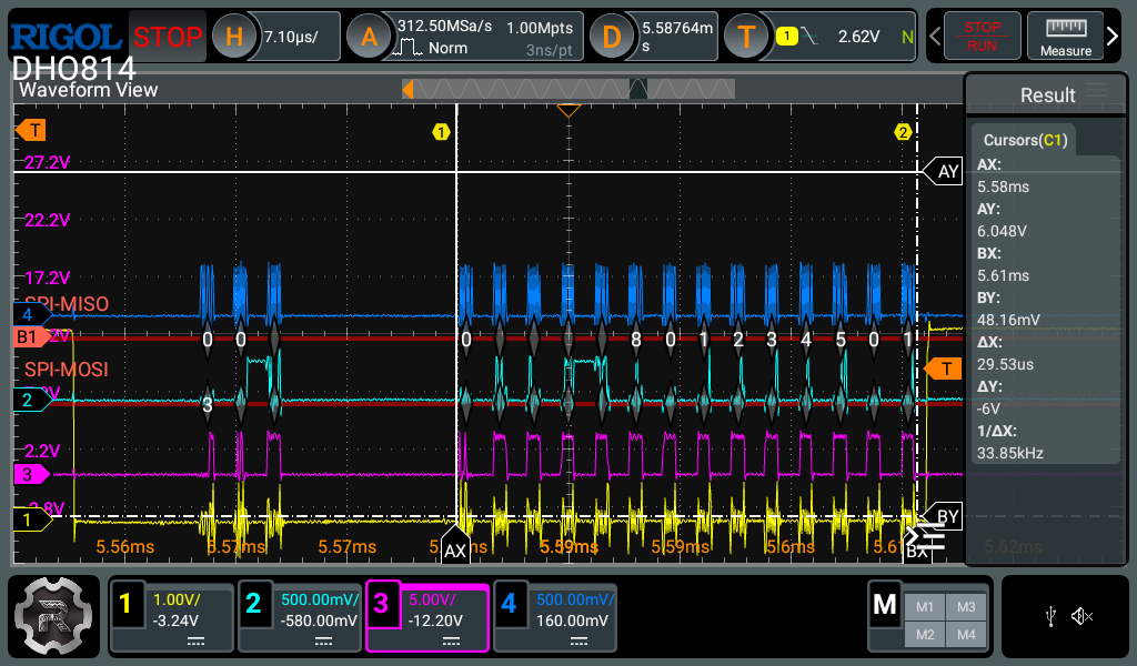
…to looking like this:
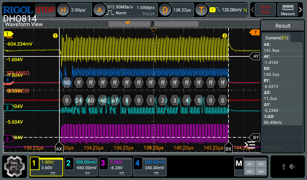
I ended up just implementing the MCP2515 driver from scratch in the main application since it was extremely simple. This was an improvement, to be certain, but there was still a lot of dead-air on either side of the transfer. What I mean is, when I timed the beginning and end of the ISR that reads an incoming CAN frame, it was apparent that a lot of the time was spent doing nothing and waiting for the SPI bus to either be acquired or released. I never dug deep enough to figure out exactly what was causing this. Something about the way that the Espressif Arduino Core handles the beginTransaction() and endTransaction() methods is seriously cycle-hungry. My understanding of these methods is that they mostly set and release a mutex so that the SPI peripheral isn’t clobbered by some process while still in use by another as well as manage the CS pin state. That doesn’t explain why it would take so long to execute. Maybe, because the beginTransaction() method takes a SPI configuration, it re-initializes the SPI master every time you call it? In any case, there was no danger of the SPI peripheral getting clobbered in our application, so I simply called beginTransaction() on initialization and toggled the CS pins explicitly. In the traces below, the yellow trace that’s being timed by the cursors is a GPIO pin that I’m toggling on and off at the beginning and end of the ISR. Everything else is SPI. You can see in the first trace that there’s a ton of time before and after the SPI traffic. Removing the calls to beginTransaction() and endTransaction() and toggling the CS pin with digitalWrite() results in the second trace.
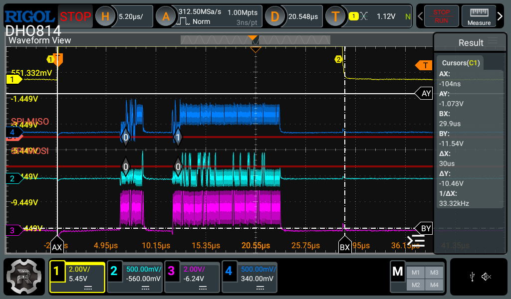
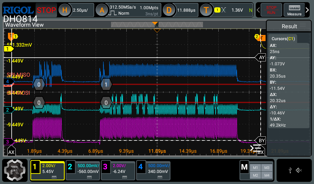
At this point, we were meeting the timing requirements to capture every frame, and I was able to hammer all six buses as fast as my CANable would allow and produce complete text logs. As an aside, the shortest interframe period that I was able to achieve with the CANable (running the stock slcan firmware) was about 40μS, this caused a small goose chase while I tried to figure out how to emulate a “fully utilized” CAN bus. Anyway, I was concerned that we didn’t have the time overhead that we needed for things like transmitting, so after some discussion we decided to split the SPI bus in two. This came at the cost of our interrupts, because it would eat up the GPIO to implement another SPI bus, but we were already dedicating an entire core to the task so we didn’t lose much by polling the controllers instead. Splitting the bus, in theory, would allow us to transact almost twice as fast by utilizing the DMA capability of the ESP32 SPI peripherals. I also used this hardware rev as an opportunity to buy some extra insurance in the form of MCP2518fd controllers. These would require a few more SPI transactions to retrieve a frame, but they could do it at over twice the speed. In exchange, we got send and recieve FIFOs on every channel. I also moved the design from two layers to four and added more test points, along with a handful of other minor changes.
That reminds me, we haven’t talked about the hardware design. Let’s look at v02.
GPIO Budget Spent
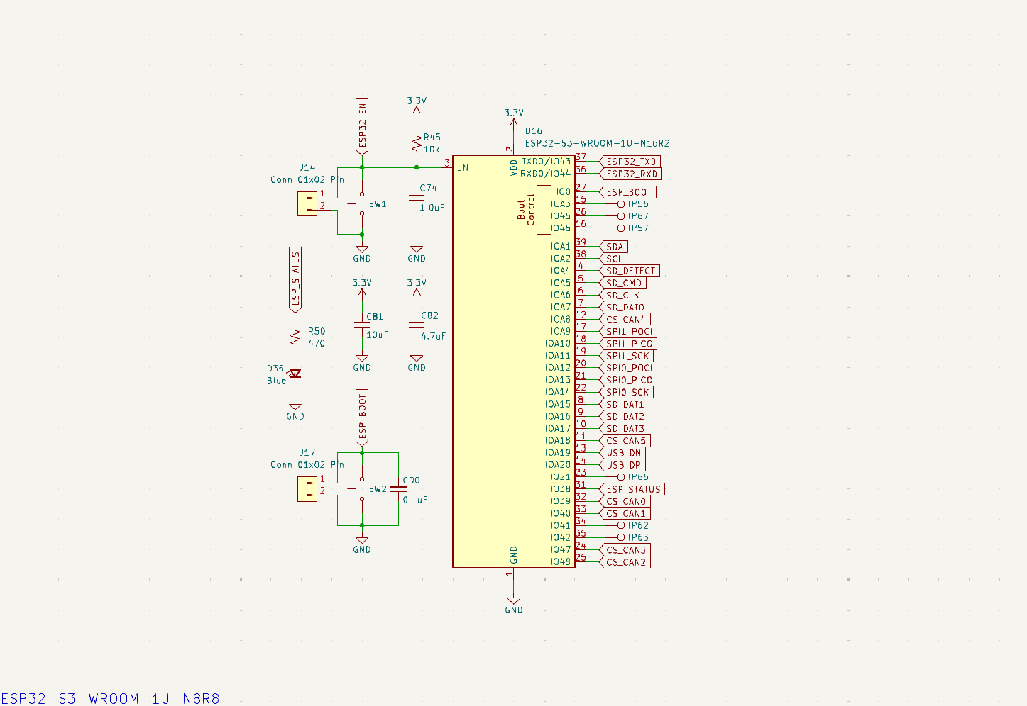
I mentioned having to sacrifice the interrupt lines from the CAN controllers in order to make another SPI bus and, looking at the ESP32 pinout, it’s obvious why. Despite having access to almost 30 GPIO, I very quickly found myself short on IO due to there being six CS pins already dedicated to the CAN controllers and seven pins dedicated to writing the SDMMC at full speed. I considered ORing all of the interrupts together for the CAN controllers on each SPI bus, but this seemed like a lot of squeezing for not much juice. Anything I could come up with to combine interrupt signals was ultimately slower than polling. There were two peripherals that didn’t need to be accessed quickly and could therefor live on an I²C bus.
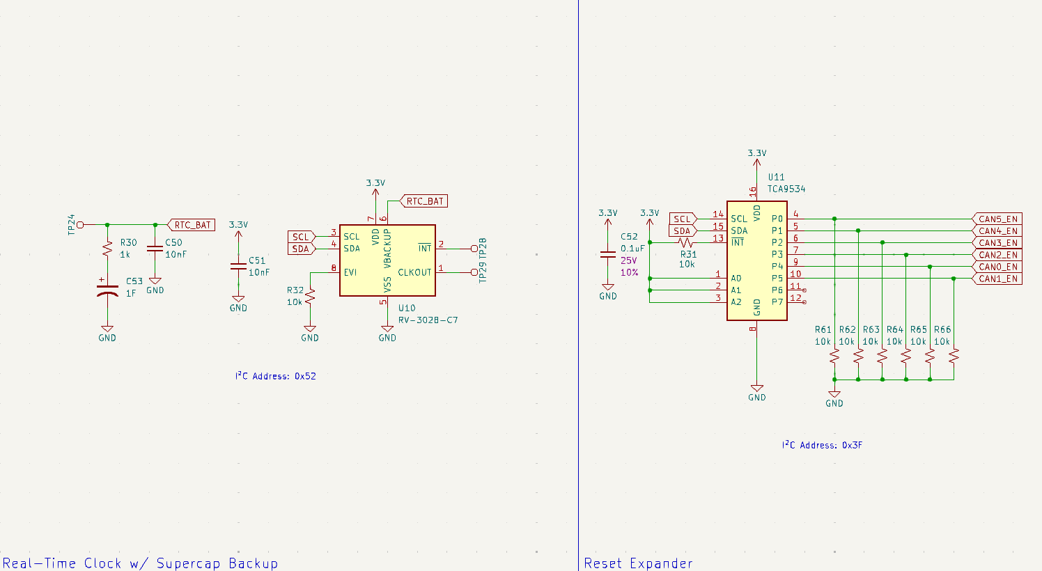
The Real Time Clock (RTC) is primarily used to keep time while the unit is powered off. Frustratingly, the ESP32S3 has an RTC, but there’s no way to supply backup power. The assumption is that it will be used in IoT applications and therefor will be able to ping an NTP server to set its clock on boot. Ultimately, the hope for our application is to extract time information from GNSS data on the CAN bus, but for the sake of timestamping our logs, it’s nice to have a good guess about the time as soon as we boot. The prototype firmware uses the RTC to set the ESP32 system time at boot and allows for the RTC to be set manually using a serial debug menu. The RTC (MicroCrystal RV-3028-C7) is backed up with a 3V 1.0F supercapacitor. In my conception of the final firmware, a task would be created to discipline the system clock by periodically setting it to the RTC and also periodically seeking to update the RTC with GNSS data from the CAN bus. It may turn out that whatever GNSS receiver is nailed down for the boat has its own cold-start RTC and will provide reasonable timestamps on startup, negating the need for an external RTC entirely.
The second peripheral on the I²C bus is a GPIO expander that consolidates all of the CAN transceiver Enable pins. I did this when I thought I had identified the transceivers as a failure point. Occasionally, under test, the CAN bus would get into an error state and wouldn’t recover. I thought having the ability to hard reset the transceivers might clear this, but it turned out to be a combination of errors in other places including the CANable USB-CAN device that was causing problems. It’s never a bad thing to have reset authority over peripherals, so it’s not hurting anything, but it may prove to be a little bit belt-and-suspenders.
CAN CAN CAN CAN CAN CAN
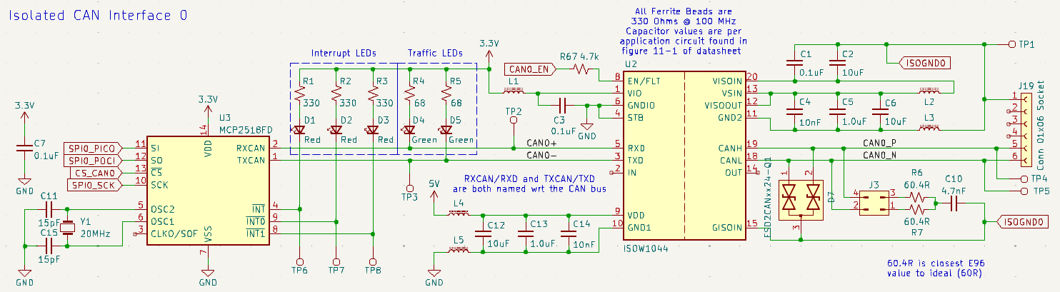
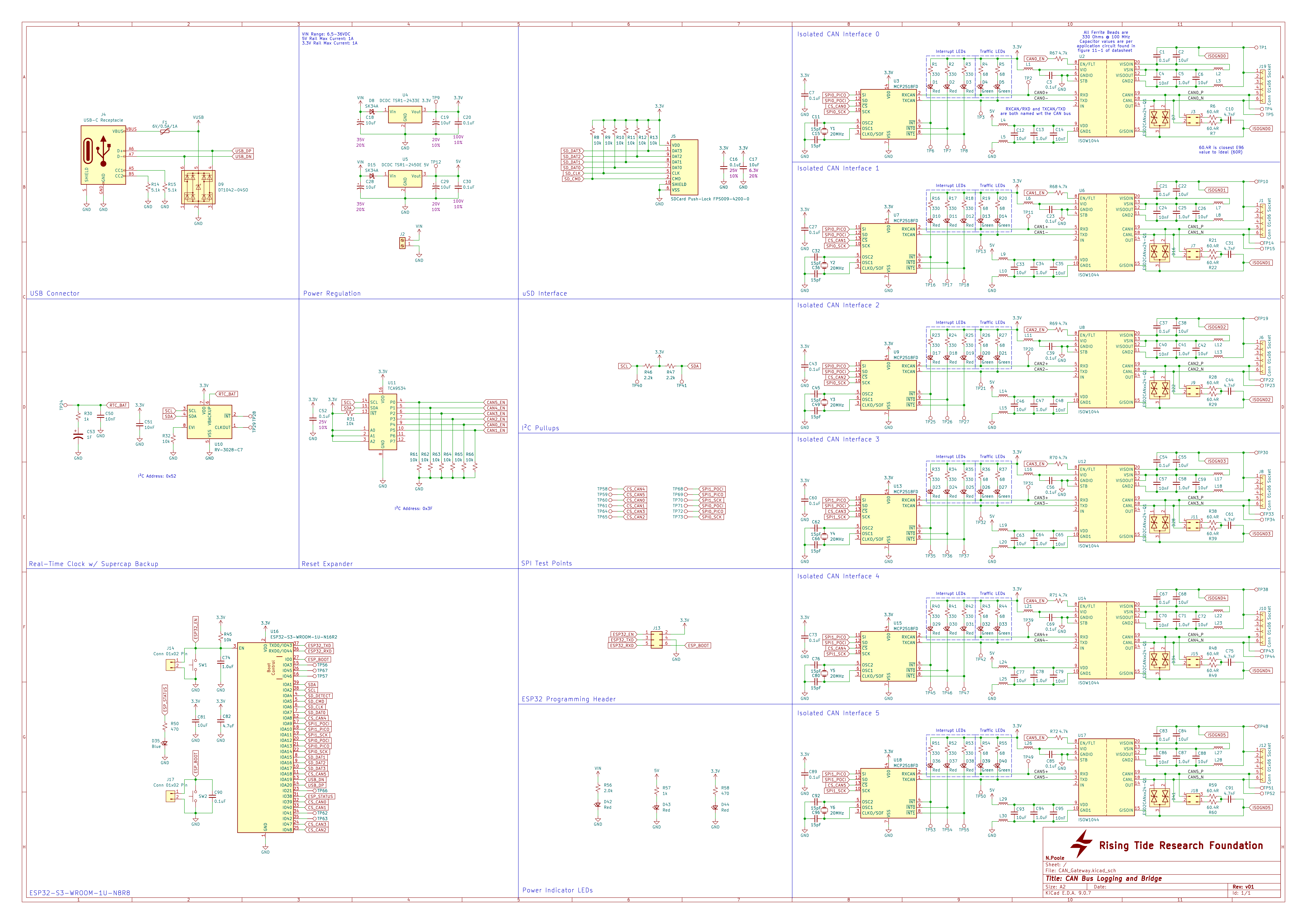
Here is one of the six CAN interfaces as implemented in v02. Paranoia about long cable runs and stray current in marinas led me to using fancy isolated CAN transceivers on the front of every CAN interface. The TI ISOW1044 provides a galvanically isolated transceiver with a built-in isolated DC-DC supply for the bus side. It’s a pretty cool part, but it does require some external ferrite beads and careful layout to take full advantage. The bus connections get the same TVS diodes and selectable split termination as I used on the load controller. The transceiver, as mentioned previously, is the Microchip MCP2518fd which provides us with configurable FIFOs to absorb traffic spikes if the ESP32 is busy, say, queueing an outgoing CAN frame. Because I had to disconnect the interrupts from the ESP32, I wanted to connect them to LEDs so they could still be used for troubleshooting. I also put LEDs on the RX and TX lines between the controller and transceiver for a visual traffic indicator, like you might see on a network switch. Although this schematic shows 20Mhz crystals on the MCP2518s, these were replaced with 40MHz crystals so that I could crank the SPI frequency to 20MHz.
Power Regulation (A heretofore unmentioned space heater)
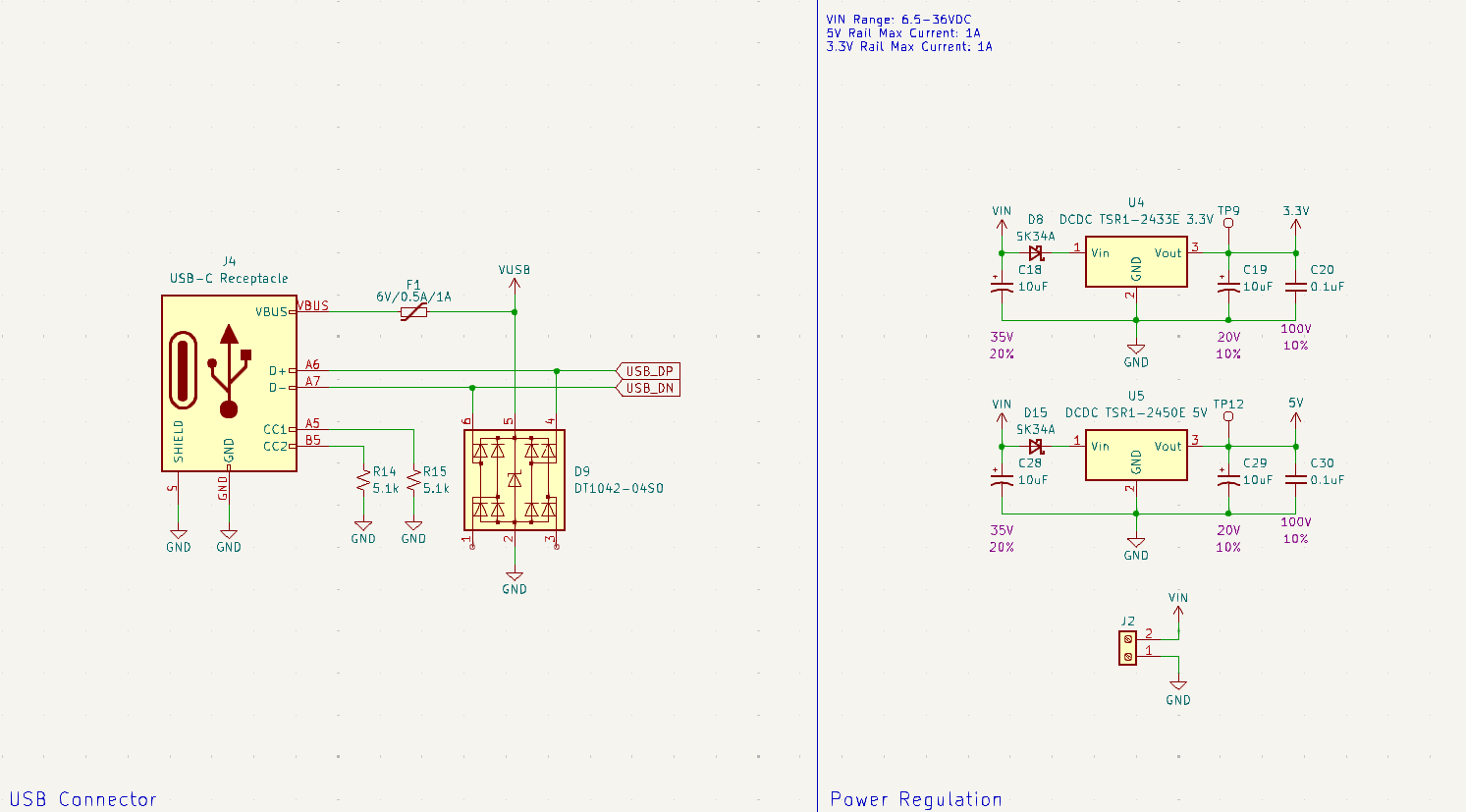
V01 complicated things by powering the 3.3V rail but not the 5V rail from the USB-C programming connector. My rationale for this was that powering the logic from the programming port would potentially make development and debugging easier, but powering the 6 DC-DC converters in the CAN transceivers could be a little more load than some USB ports would be happy with. A separate 3.3V LDO and an arrangement of diodes did make this possible, but it made sense to ditch them for simplicity in v02. I’m noticing now that there’s still a vestigial PTC on the VUSB net. In any case, I wanted anything designed for the boat to be compatible with either a 12V or 24V auxiliary power bus. Dropping that much voltage was a big ask for a linear regulator, especially when also asking for a lot of power overhead in case the Gateway was press-ganged into powering other peripherals over the CAN cabling. Too big an ask, it turns out. Both the load controller and this design originally used LM1085 linear regulators, but they would dissipate too much power as heat, making the board inefficient and requiring heat-sinks. Linear regulators are not efficient in the best circumstances, but dropping up to 24V down to 3.3V… that’s my bad, honestly.
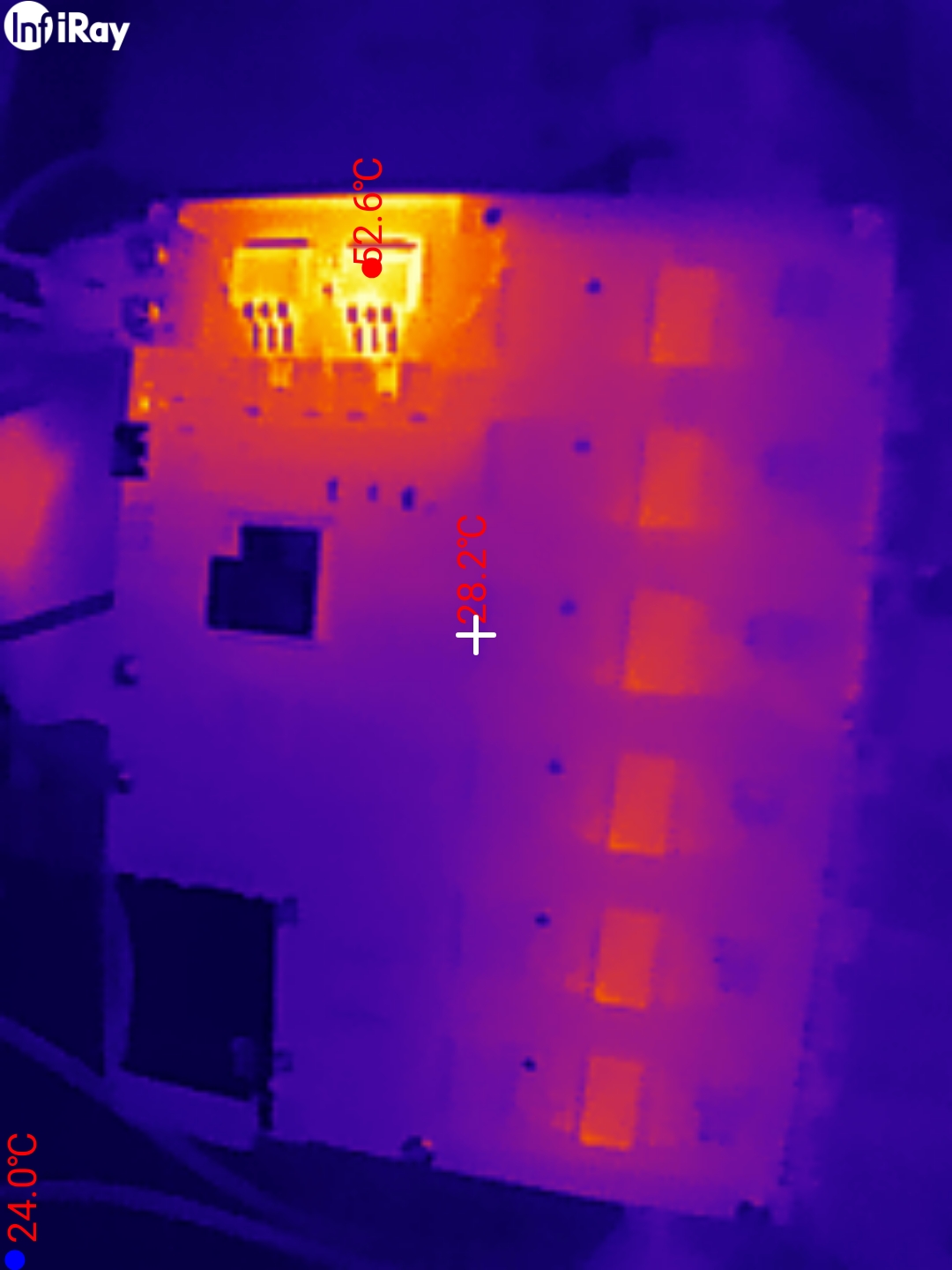
So in v02, the linear regulators were replaced with switching regulators. These little Traco Power TSR1 converters are designed as drop-in replacements for TO220 package linear regulators (although they weren’t pin compatible with the LM1085, unfortunately). They’re good for an Amp of output and have a wider input voltage range than the linear regulators. Dropping these in cut the design’s power consumption by a third at 12V.
Considering Alternatives and the VCU
After some difficulty getting v02 to behave as reliably as v01, mostly due to the relative complexities of initializing and communicating with the MCP2518fd over the MCP2515, several discussions were had about alternative implementations of the CAN Gateway. An early suggestion was to use off-the-shelf CAN-Ethernet gateways and a little Linux box of some kind. Frankly, this was a great suggestion, but it didn’t look much like “novel technology development” and, honestly, hardware design is often the fun part of my job. We stuck with designing our own hardware, but I began to push for revising to a more powerful SoC or SoM. We all had concerns that the added complexity of something like an embedded Linux SoM might also bring instability, which is definitely a consideration. Fault tolerance and recovery is always a concern, but to what degree really depends on how critical the inter-bus CAN communication is going to be. Frankly, I think there were concerns about bring-up time for a new design because of the slow pace of development on the ESP32. I’m confident that developing on an exponentially more powerful platform, in an environment that I’m familiar with, would actually have accelerated development significantly. It would also make the code much more transportable because of the added layers of obfuscation. By this point, we had begun to think of the CAN Gateway not just as a CAN switch and data logger, but as a VCU (Vessel Control Unit) which will inevitably take on more features and responsibilities as development progresses. Whatever the VCU ends up being, I suspect it will run Linux. We eventually decided to continue firmware development on v02 of the CAN Gateway to at least data logger functionality.
Prototype Logging Firmware Release
After a lot of adjustments to Seeed Studio’s CAN-BUS library, and a consultation with another engineer who had done some contracting with the foundation, I finally put together a reasonably useful logging firmware. With some optimization to the SPI process, it was found that the limiting factor causing my CAN frame drops was actually the circular buffer that I was using to transfer the frames between cores. It’s still unclear why the buffer is overflowing. I’ve since replaced my naive implementation with a FreeRTOS Queue based implementation at Gus’ suggestion. This dropped fewer frames when overflows did occur and gave me better visibility into when it was happening. I suspect something is slowing down the main application core that’s out of my control. The ESP32 has a lot of system tasks to attend on core 0, so it’s possible that I need to explicitly kill the protocol stack processes for the unused Wi-Fi and Bluetooth. We also relaxed our timing target because “bulletproof” seems like it may be too big of an ask. After all, if we find ourselves with 6 CAN buses all at 100% duty with 0-byte frames, we have bigger problems.
With the logging firmware wrapped up and documented for release, I exported the binaries and wrote a little batch script to program the board without having to install Arduino, etc. just to improve user experience on the West Coast at integration time. That got pinned to the GitHub release and a milestone was complete.
Inbox/Outbox
The next challenge facing the v02 hardware is transmitting CAN frames as well as receiving them. I was asked to prototype an implementation of this behavior and I had it working poorly just before my contract was ended. I actually implemented a prototype of the “macro” architecture that I envisioned for the final hardware. The idea being that incoming frames on all buses are compared to a list of IDs which are assigned “macros,” little bits of code that can transform the frame data, do math, and queue outgoing frames. Eventually, it would be cool if these macros were interpreted at runtime and lived on the SD card or flash storage. I’ve been told that Lua is a likely scripting candidate for this because of its small footprint.
In my prototype implementation, I just wrote the macros as functions and created a struct that relates a frame ID, a bus ID, and a function, like so:
struct frameTemplate
{
  uint8_t matchChannel;
  uint32_t matchID;
  void (*macro)(CANFrame matchedFrame);
};

const frameTemplate templates[] = {
  {0, 0x305, testMacroStd},
  {0, 0x1CEF24E1, testMacroExt}
};
Whenever a frame is popped off the RX queue, we iterate over an array of these structs, look for a match on both the bus ID and frame ID, and call the attached function with the received frame.
    for (uint8_t tempidx = 0; tempidx < templateCount; tempidx++)
    {
    if (templates[tempidx].matchChannel == frame.channel && templates[tempidx].matchID == frame.id)
    {
        templates[tempidx].macro(frame);
    }
    }
There is undoubtedly a more elegant solution, but this does result in our “macros” getting called. For reference, here are the test macros in question:
void testMacroStd(CANFrame matchedFrame)
{
  TxFrame outFrame;
  outFrame.channel = 1;
  for (uint8_t i = 0; i < 8; i++)
  {
    outFrame.data[i] = matchedFrame.data[i];
  }
  outFrame.dlc = matchedFrame.dlc;
  outFrame.ext = matchedFrame.ext;
  outFrame.rtr = matchedFrame.rtr;
  outFrame.id = 0x405;

    // Attempt to queue up the outgoing frame
  if (!xQueueSend(canTxQueue, &outFrame, 0))
  {
    // CAN TX queue is full, the other task will log this as a warning
    canTxOverflowCount++;
    canTxOverflowInterval++;
  }

  return;
}

void testMacroExt(CANFrame matchedFrame)
{
  TxFrame outFrame;
  outFrame.channel = 2;
  for (uint8_t i = 0; i < 8; i++)
  {
    outFrame.data[i] = matchedFrame.data[i];
  }
  outFrame.dlc = matchedFrame.dlc;
  outFrame.ext = matchedFrame.ext;
  outFrame.rtr = matchedFrame.rtr;
  outFrame.id = 0x1CEEFF00;

    // Attempt to queue up the outgoing frame
  if (!xQueueSend(canTxQueue, &outFrame, 0))
  {
    // CAN TX queue is full, the other task will log this as a warning
    canTxOverflowCount++;
    canTxOverflowInterval++;
  }

  return;
}
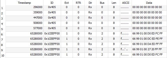
…and here is the resulting traffic in SavvyCAN, sorted by channel:
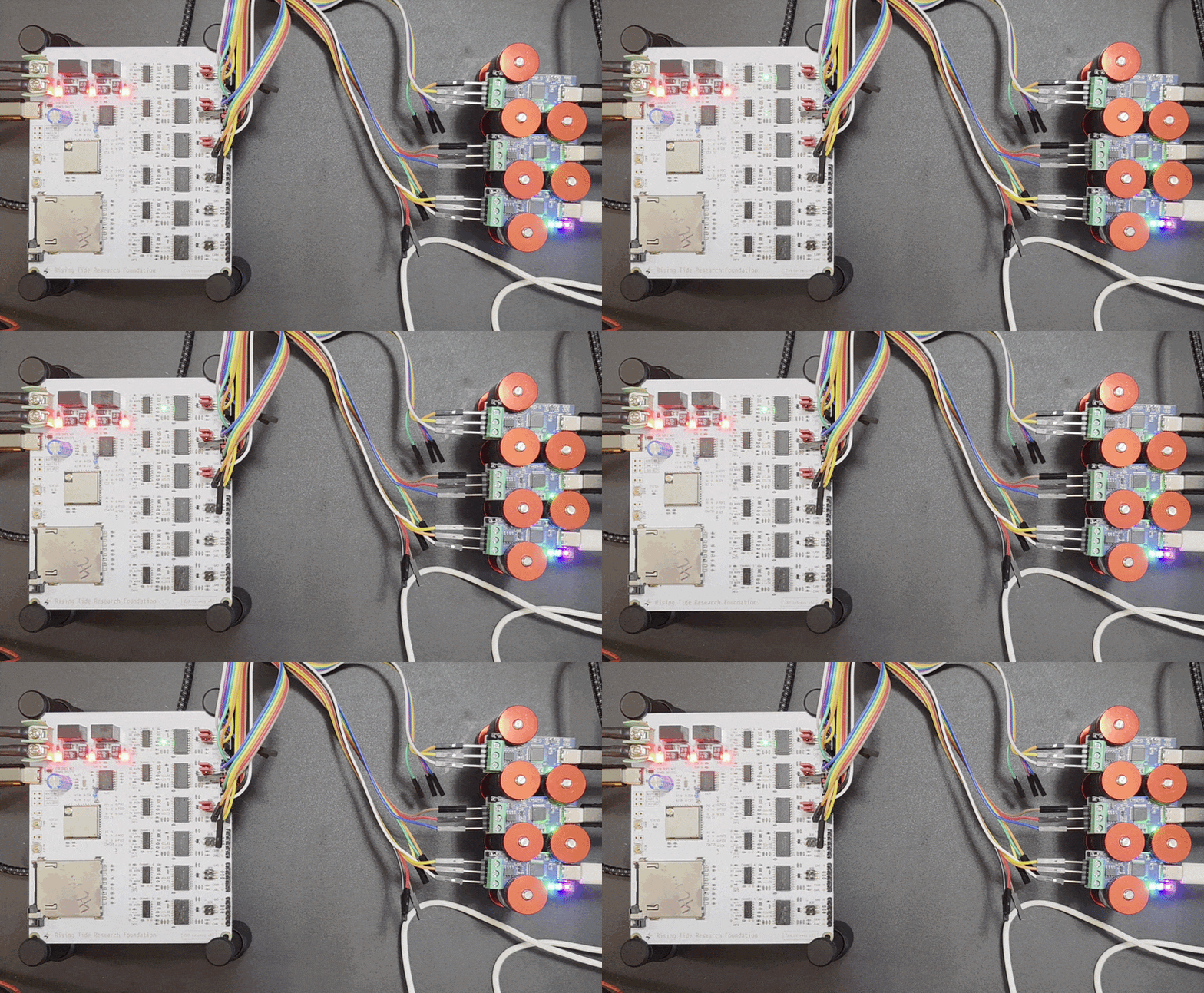
And how about some blinkenlights from this CAN transaction to wrap up this section?
Honorable Mention: Project Management
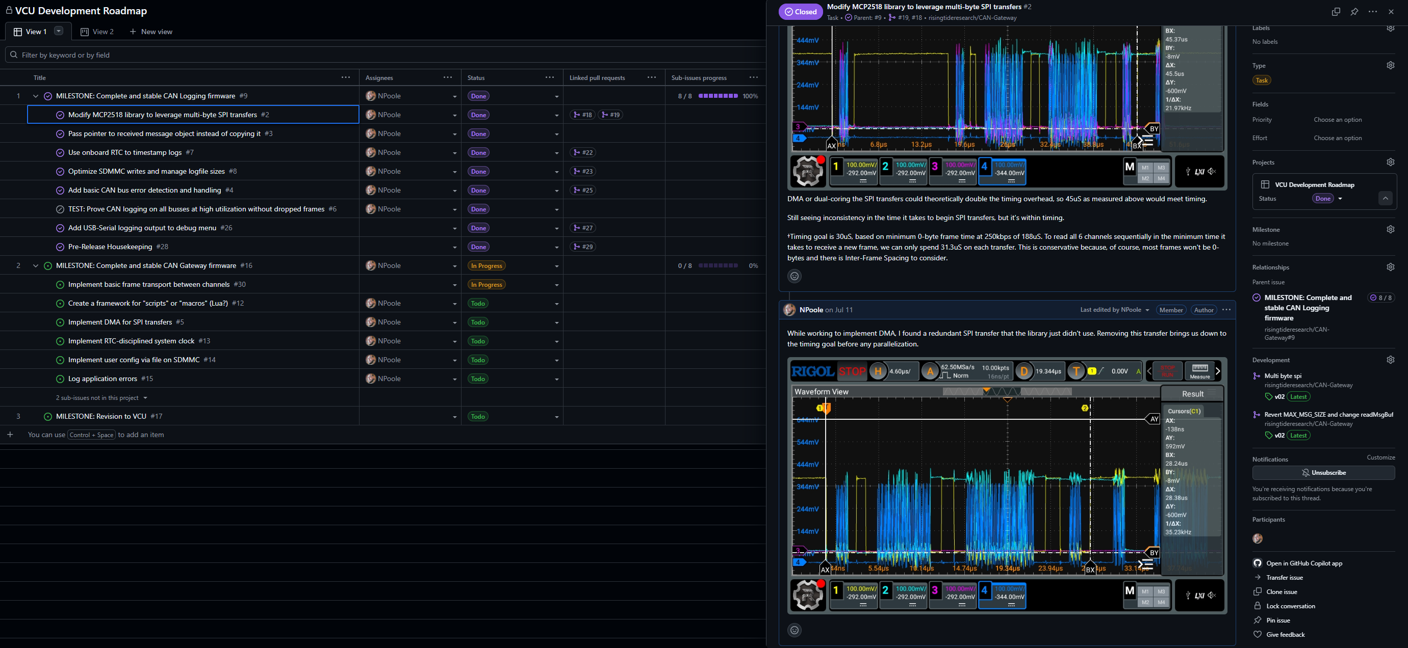
Working in a mostly self-guided way, I’ve come up with a lot of different systems for keeping myself on task. The most effective of these is still whiteboarding. I have a rolling whiteboard in my office where I keep my long-term TODO, which I break down into smaller tasks as I make room. This turns out to be a pretty good way to keep the status of a project in my head, but it’s not very effective at making that status available to others. After chatting with the founder about how to offer more visibility into my progress, I decided to try creating a GitHub Project for the CAN Gateway development. I’m actually trying to move away from GitHub for personal use because of AI overreach (I’ve just migrated my work to Codeberg) but the foundation was already using it, so finding a project management tool built in to something we were already using made sense. I have to say, even though I probably used it wrong, I found Projects to be a really useful tool. The ability to create a roadmap with tasks and subtasks which are connected to Git pushes and PRs is really powerful, and using Issues to document progress on tasks along with information like scope traces and links makes documentation really easy. I think there’s an equivalent “Projects” framework on Codeberg, and I’ll be checking it out.
Moving On
For financial reasons, I’m told it no longer makes sense for the foundation to hold on to remote hardware devs who can’t be on-site to help with integration. For what it’s worth, I was given plenty of heads-up that my contract would not be renewed, and it feels good to leave the foundation on good terms. Hopefully I’ll be able to work with them again in the future, I think what they’re doing is really cool. What’s next for me? I don’t know yet! If you have a project that you think I could help with based on what you just read, shoot me an email or check out my CV linked in the nav bar at the top of the page!