Building an Oxikit O2 Concentrator (Part 2)
Scroll DownAssuming Control
My previous post left off with the oxygen concentrator mechanically complete. All it needed was some electronics to control the solenoid valves. The PSA cycle is so simple that you could easily implement the entire controller in ladder logic on a PLC, or even in discrete timers. That said, I do PCB layout and a lot of Arduino programming for a living so I chose to build my own little Arduino-based solution.
Arduino on (DIN) Rails
I chose to mount all of the electronics for this project on DIN rail. If you’re not familiar with DIN rail, it’s a standardized size and shape of metal rail that’s used to mount industrial control modules. It’s called DIN rail because it was originally spec’d by Deutsches Institut für Normung.
What’s cool about DIN rail is that because it’s a popular standard, there are a lot of commercially available components from varying industries that are designed to fit it. In a way, it’s industrial control LEGO. Also, anything that isn’t already designed for DIN mount can be adapted using clip-on mounting adapters!
Here’s a rendering of the Arduino breakout that I designed for this project. There’s not much to it! It’s really just a screw terminal breakout for the Pro Micro C with a few extras thrown in. Two of the ADC inputs are shifted down with resistor dividers and protected with Schottky Diodes to accommodate 10V sensors. There aren’t any sensors on the system currently, but I can imagine adding some pressure monitoring down the line so it made sense to lay some groundwork. There’s also a pair of dual-MOSFET chips providing four outputs that are capable of sinking several amps at 30V. These allow the Pro Micro to switch the solenoid valves at 12V.
The board is designed to fit into an inexpensive DIN PCB carrier so it will mount alongside the rest of the DIN modules.


The Rest of the DIN modules
…speaking of which, there’s more to the electronics than just the Arduino breakout. Here’s a shot of every module mounted on a piece of rail, just to make sure they would all fit, before they’re wired up.

On the left, you can see the Arduino breakout in its DIN carrier and then there are a few other things hanging out. Let’s go over them from left to right.
Solid State Relay
This relay allows one of the outputs on the control board to switch the 120VAC power to the air compressor. I wanted to give the controller domain over the compressor both for convenience (a standby switch can turn the entire system on and off) and for safety (a future pressure monitoring system could shut off the compressor if there was an overpressure in one of the sieve beds or the buffer tank).
5VDC Power Supply
The control board needs 5VDC to operate, and while I could have built a switching supply on board itself, it was more convenient to just snap on a MeanWell supply. Besides, this way it’s modular. If the 5V supply dies for some reason, I can replace it without doing rework on the control board. This is the smallest DIN mount 5VDC supply that MeanWell makes and it’s still over-spec for the control board, so there’s plenty of overhead for other 5V accessories in the future.
12VDC Power Supply
12VDC is used to activate all of the solenoid valves on the system. It’s also needed for the cooling fans on the condenser coil. This MeanWell supply is good up to 5A which is plenty.
Circuit Breaker
The air compressor is not gigantic, but it is quite a load on startup, so it seemed prudent to put a 20A breaker on it just in case it got stalled somehow. Is there likely a 20A breaker on whatever circuit you plug the machine into? Sure. This seemed like cheap insurance, though, and also gave me an easy way to manually switch the compressor on and off during testing.
Terminal Blocks
Several modules on the DIN rail need access to the 120VAC line. These terminal blocks give me an easy way to distribute the mains voltage to everything that needs it.
Putting It All Together
Here’s a little diagram to explain how everything was wired together. It’s a bit of a rat’s nest but it’s very straight-forward. Mains voltage comes into the terminal block where it’s distributed to the compressor through a breaker as well as both of the DC power supplies. The 12V supply feeds the cooling fans and the solenoid valve MOSFETs on the control board. The 5V supply feeds the control board. And finally, the solenoid valves also connect to the controller.

Controller Firmware
The controller firmware I used was taken directly from the Oxikit project. This is something I’ll probably change if I end up adding sensors and safety features down the line. The firmware as provided is intentionally very utilitarian, spartan, easy to parse. Have a look.
// Full program for Arduino Uno control of Oxycon Relays and LCD units.
// Edited: 05/11/20
// Author: Robert Danger Byrd
// For Version 5 AKA "Handy Oxy"


// RELAY PIN ASSIGNMENT
//**************************************************************************
int Sieve_A_Valve = 5; //Defined Pin as Variable
int Sieve_B_Valve = 6; //Defined Pin as Variable
int PreCharge_Valve = 7; //Defined Pin as Variable
int Fan = 8; //Defined Pin as Variable

// VARIABLE CREATION
//**************************************************************************
unsigned long Relay_Test_Delay; //delay variable creation
unsigned long Startup_Purge_Delay; //delay variable creation
unsigned long Production_Delay; //delay variable creation
unsigned long Flush_Delay; //delay variable creation
unsigned long PreCharge_Delay; //delay variable creation

//**************************************************************************
void setup()
{


  // STARTUP
  //**************************************************************************
  // Serial Port initialization
  Serial.begin(9600);


  // SET PIN MODE FOR PINS IN PROGRAM
  //**************************************************************************
  pinMode(Sieve_A_Valve, OUTPUT);
  pinMode(Sieve_B_Valve, OUTPUT);
  pinMode(PreCharge_Valve, OUTPUT);
  pinMode(Fan, OUTPUT);


  //  SET DELAY TIMING HERE
  //**************************************************************************
  Relay_Test_Delay = 0;
  Startup_Purge_Delay = 1000;
  Production_Delay = 4000;
  Flush_Delay = 450;
  PreCharge_Delay = 700;

  // VALVE RELAY TEST SEQUENCE
  //**************************************************************************
  Serial.println("Relay Test Sequence");
  digitalWrite(Sieve_A_Valve, HIGH); //Turn on relay
  delay(Relay_Test_Delay);
  digitalWrite(Sieve_B_Valve, HIGH); //Turn on relay
  delay(Relay_Test_Delay);
  digitalWrite(PreCharge_Valve, HIGH); //Turn on relay
  delay(Relay_Test_Delay);
  Serial.println("Valve Relay Test Sequence Complete");
  delay(Relay_Test_Delay);


  // STARTUP PURGE
  //**************************************************************************
  Serial.println("Relay Test Sequence");
  digitalWrite(Sieve_A_Valve, HIGH); //Turn on relay
  digitalWrite(Sieve_B_Valve, HIGH); //Turn on relay
  digitalWrite(PreCharge_Valve, HIGH); //Turn on relay
  delay(Startup_Purge_Delay);


  // FAN CONTROL
  //**************************************************************************
  Serial.println("Program Starting...");
  delay(Relay_Test_Delay);
  digitalWrite(Fan, HIGH);
  Serial.println("Fan Switched On");
}

void loop()
{

  //CYCLE 1
  //**************************************************************************
  Serial.println("Sieve A Charge / Sieve B Purge");
  digitalWrite(Sieve_A_Valve, HIGH);
  digitalWrite(Sieve_B_Valve, LOW);
  digitalWrite(PreCharge_Valve, LOW);
  delay(Production_Delay);


  //CYCLE 2
  //**************************************************************************
  Serial.println("Sieve A Charge / Sieve B Purge / Flush/PreCharge");
  digitalWrite(Sieve_A_Valve, HIGH);
  digitalWrite(Sieve_B_Valve, LOW);
  digitalWrite(PreCharge_Valve, HIGH);
  delay(Flush_Delay) ;


  //CYCLE 3
  //**************************************************************************
  Serial.println("Sieve A Charge / Sieve B Charge / Flush/PreCharge");
  digitalWrite(Sieve_A_Valve, HIGH);
  digitalWrite(Sieve_B_Valve, HIGH);
  digitalWrite(PreCharge_Valve, HIGH);
  delay(PreCharge_Delay);

  //CYCLE 4
  //**************************************************************************
  Serial.println("Sieve A Purge / Sieve B Charge");
  digitalWrite(Sieve_A_Valve, LOW);
  digitalWrite(Sieve_B_Valve, HIGH);
  digitalWrite(PreCharge_Valve, LOW);
  delay(Production_Delay);

  //CYCLE 5
  //**************************************************************************
  Serial.println("Sieve A Purge / Sieve B Charge / Flush/PreCharge");
  digitalWrite(Sieve_A_Valve, LOW);
  digitalWrite(Sieve_B_Valve, HIGH);
  digitalWrite(PreCharge_Valve, HIGH);
  delay(Flush_Delay);


  //CYCLE 6
  //**************************************************************************
  Serial.println("Sieve A Charge / Sieve B Charge / Flush/PreCharge");
  digitalWrite(Sieve_A_Valve, HIGH);
  digitalWrite(Sieve_B_Valve, HIGH);
  digitalWrite(PreCharge_Valve, HIGH);
  delay(PreCharge_Delay) ;

}
So, yeah. It sets up Serial for debug messages, defines some delays, and then loops through the PSA cycle. The philosophy here is probably that a complicated firmware is just a possible source of bugs and that if the system has a problem, we’ll probably notice by either the sound of the cycle or the quality/quantity of the O2 output. This system was created as an emergency stopgap for medical O2 production in COVID-stricken India, so keeping it simple and approachable for anyone who needs to build or maintain it takes priority over concise code, fancy watchdogs, safety interlocks, etc.
In the future, I’d like to integrate an O2 sensor and a flow sensor on the output line so that the machine can adjust its own valve timing in realtime to maintain a set output volume or quality. A system with a larger buffer tank could even use pressure sensors and valve control to shut off the compressor when oxygen demand is lower. In the meantime, running the machine in continuous mode with fixed tunings is just fine to fire up a few torches.
Cool Dry Air Redux
After wiring everything up and programming the controller, I brought up the system piece-by-piece. First I ran just the valves controller, then the controller and the valves, then everything together with the compressor. Running the compressor for a few minutes made two things apparent: the safety valve works and the condenser is going to get HOT. Of course, we expect the condenser to get hot but I wanted to feel it myself before selecting a cooling fan for the final assembly. Feeling the top of the condenser, I knew we would need significant airflow, but not hurricane force winds. Even without active cooling, the bottom of the coil was staying just above ambient temperature, so with just a little bit of help I figured the coil would be doing its job.
After looking around at what was available, I finally landed on bolting a bunch of computer fans together. I know this sounds like a hack, but it’s hard to find large, low-profile, high-flow cooling fans. I did consider an electric automotive radiator fan, which would probably work, but I wanted something skinny enough to fit inside the condenser coil so that there wasn’t a big spinning fan blade hanging off the front of this thing. Bolting together a bunch of smaller fans also gave me the option to add down-facing fans to cool the compressor heads.
I designed some parts that I could print on my 3D printer to bolt the fans together and ended up with this monstrosity.

After a lot of fiddling around with the mounting, I finally managed to get the fan stack suspended in the middle of the condenser coil. With the cooling in place, another potential problem showed up: The condenser works really well and the air here is really wet. The coalescing filter at the bottom of the coil is doing a good job catching water, but the mistiness inside the catch-cup made me a little nervous about the humidity of the air heading into the bottom of the sieve beds. To address this, I added a desiccant dryer in-line after the coalescing filter and filled it with fresh desiccant.

Not only will this keep the air dry, but because the desiccant changes color as it gets saturated, it will act as a visual indicator for how much of a water problem I actually have.
Complete Assembly
System Tour
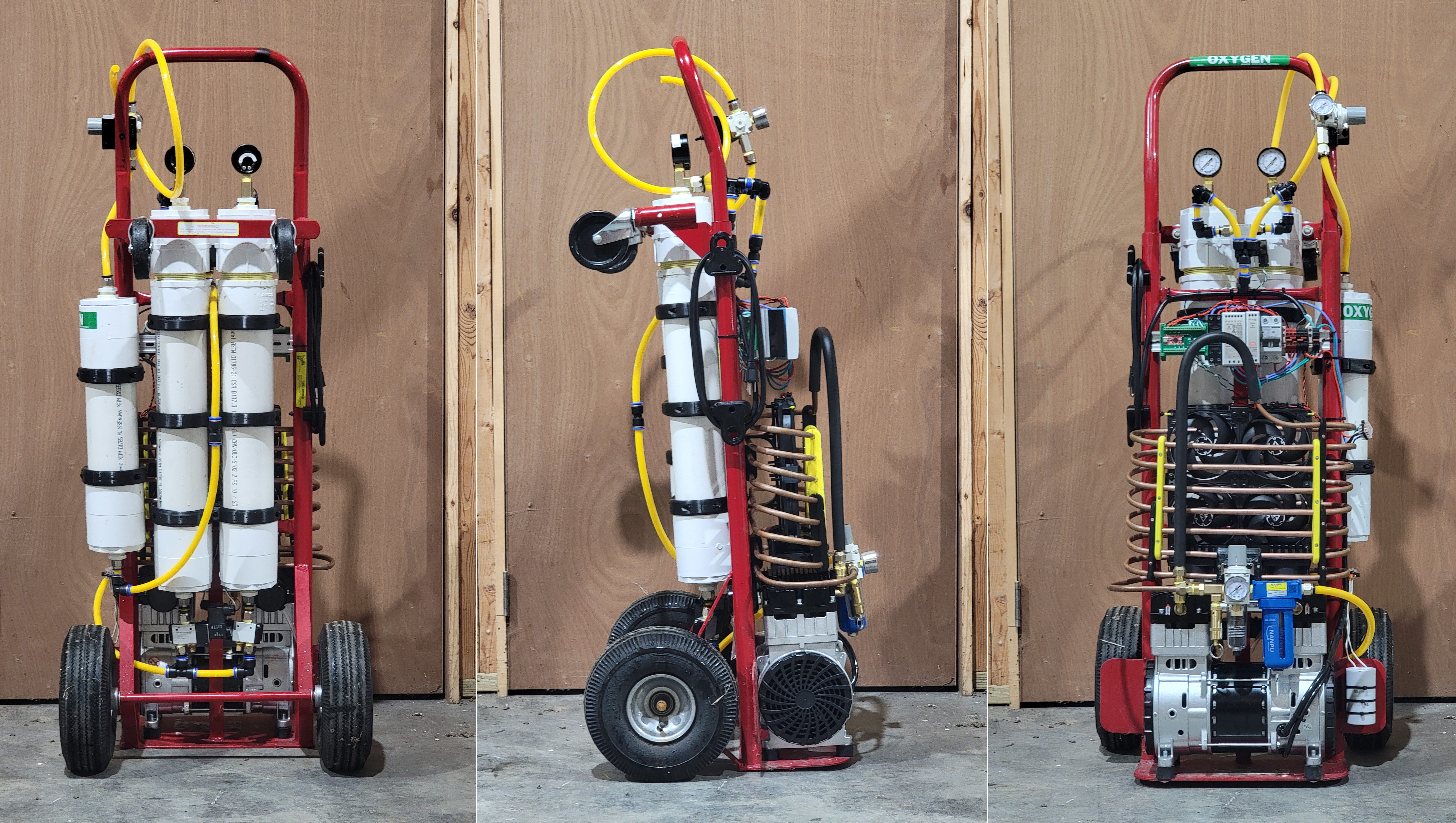
Here is an illustration of the completed system that I think is a little easier to parse than the original photograph. Let’s take on last tour of the whole thing now that it’s all in one piece.

From bottom to top: The 2HP oil-free electric air compressor sits on the base of the hand-truck that serves as the frame. The running capacitor for the compressor is mounted to the side. Just above that is the condenser coil made from 25’ of 3/8” soft copper tubing. The first section of the condenser is covered in an insulating foam sleeve to prevent condensation from collecting in the riser and dripping into the compressor. At the end of the condenser is a safety valve to keep the system pressure below 40psi. After that, a coalescing filter to remove condensed water from the air stream and a desiccant dryer to catch any remaining humidity.
Suspended in the middle of the condenser coil is the cooling fan stack. This comprises 4 120mm fans pulling air across the coil and 2 80mm fans blowing air down onto the compressor heads.
On the back of the frame, I’ve mounted the sieve beds, which can be seen poking up over the top of the power and control section. The buffer tank sits on the side of the frame (and got a green OXYGEN sticker). On the other side of the frame, I mounted some 3D printed cord keepers for the power cable.
The DIN rail with all of the power and control modules lives just above the condenser. The existing cross-beam on the hand-truck makes a convenient support for securing wires.
Above the DIN section you can see the output end of the sieve beds with their respective pressure gauges. And then on the handle of the hand-truck, a 3D printed mount for the output pressure regulator.
How To Test It
So how do we know it’s making oxygen? Well, there are quantitative methods: Electronic O2 Sensors, chemical titrations, etc. But it’s not actually important to me at this point what the exact concentration is, I just need it to feed a torch. Eventually, I’ll likely invest in an O2 meter so I can tune the system and get the most out of my zeolite, but the first tests will just be determining whether oxygen enriched air is coming out of the output at all.
My first test was just the first thing that came to mind. I rolled up a piece of printer paper and lit it on fire, allowing it to burn out and smolder before dropping it into a pyrex measuring cup. Then I turned on the system and attached a piece of hose to the output, aiming it into the measuring cup. Sure enough, the smoldering paper began to burn so brightly that it was hard to look at, leaving behind a white ash.

With confirmation that the air coming out of the system was indeed enriched, I moved on to testing a small oxy-fuel torch. I cut the oxygen fitting off of a Mag-Torch brazing torch and jammed the hose into the output on the concentrator. Without a check-valve or a flashback arrestor of any kind, I was very careful to keep the test short and to pay attention to the order in which I was pressurizing and depressurizing the fuel and oxygen. After tweaking the output regulator, I was able to make a steady blue flame using MAPP gas as my fuel source. MAPP burns a lot like Acetylene with a yellow, sooty flame at atmospheric pressure and oxygen, so the fact that the resulting flame was sharp and blue with no soot suggests an adequate oxygen concentration.

Encouragingly, I had to dial the output regulator way down to keep from blowing out the torch, meaning that there’s a lot more capacity on tap.
Finishing Touches
Before I press this machine into service, there are a few things that need to happen. First, I need to assemble an oxy-fuel manifold for my torches. Parts are en route for that project now. The manifold will allow me to keep my torches connected and adjusted with ball valves to switch them on and off, it will also have needle-valve controlled outputs on the fuel side for things like bunsen burners. On top of that, the manifold will act as a convenient point to attach flashback arrestors for the entire system. I’ll post more on the torch manifold after it’s completed.
Another last minute addition to the machine will be an hour meter to keep track of how many hours of service the sieve beds have seen. This will help me determine how much life can be squeezed from a batch of molecular sieves. Down the road, after I have an idea of how long they should last, the hour meter will act as a diagnostic tool. If the zeolite is wearing out too fast, there’s a problem.
Sauce?
I don’t have a step-by-step assembly guide or anything, but if you’d like to get your hands on any of the original work I did for this project including the CAD files or PCB layouts, you can find it in the github repo. Anything that’s missing from my documentation of this project can probably be found in the original Oxikit documentation.